作者
Ivan Chien
始于
分类:CG
Tags: [ CG ]
始于
分类:CG
Tags: [ CG ]
Learn OpenGL
Shaders
The Graphics Pipeline
Sections:
- Vertex shader. Input single vertices, transform their 3D coordinates to different 3D coordinates (via viewport matrix?), process attributes.
- Primitive assembly. Assemble the primitive shape with all vertices.
- Geometry shader. Can emit new more vertices and generate primitives.
- Rasterization stage. Maps the resulting primitives to the corresponding pixels, do clipping.
- Fragment shader. Calculate color of a pixel, and be usually where the effects occur.
- Alpha test and blending.
Vertex Buffer Objects
A vertex buffer object (VBO) is the memory space in the GPU which can store a large number of vertices.
An Example of Fragment Shader
#version 330
out vec4 FragColor;
in vec3 outColor;
in vec3 outPos;

// uniform varibles like global variables
// the `seed` is a value in the range of [0, 1] generated by a periodic function,
// maybe `sin`, but here is a zig function written by myself
uniform float seed;

// most of codes are like C language
float pow2(float a)
{
    return a * a;
}

float distance(vec2 a, vec2 b)
{
    return sqrt(pow2(a.x - b.x) + pow2(a.y - b.y));
}

void main()
{
    // preprocess coordinate, make it easy to transform to the polar coordinate
    float x = outPos.x;
    float y = outPos.y + 1 / 8.;

    // `const`s in GLSL are compile-time constants,
    const float r = 5 / 8.;
    // so here can't use `const`.
    float theta = seed;
    const float pi = 3.1415926f;

    // convert three polar coordinates to Cartesian coordinates
    vec2 rPoint = vec2(r * cos(theta), r * sin(theta));
    vec2 gPoint = vec2(r * cos(theta + 2 * pi / 3), r * sin(theta + 2 * pi / 3));
    vec2 bPoint = vec2(r * cos(theta + 4 * pi / 3), r * sin(theta + 4 * pi / 3));

    // calculate the factors of RGB of one of points
    vec2 point = vec2(x, y);
    float fR = 1 - distance(point, rPoint) / r / 2;
    float fG = 1 - distance(point, gPoint) / r / 2;
    float fB = 1 - distance(point, bPoint) / r / 2;

    // assign the out variable fragment color
    FragColor = vec4(fR, fG, fB, 1);
}
Vertex Array Object
Vertex array objects (VAO) are like context managers, they point to VBOs which have been bound and store their buffer data and structures, then you can switch between different vertices’ data and configurations via binding different VAO.
Coordinate System
Overview
To transform the coordinates from one space to another coordinate space, we’ll use several transformation matrices like model, view and projection matrix:
- Model matrix. From local space to world space.
- View matrix. From world space to view space (aka. camera space or eye space).
- Projection matrix. From view space to clip space. The view box Which created by the projection matrix is called frustum
(平截头体) . We can select one projection matrix between orthographic projection matrix and perspective projection matrix. - Viewport matrix. From clip space to screen space.
So, the formula that convert a local space coordinate to clip space coordinate is:
\[V_{clip} = M_{projection} \cdot M_{view} \cdot M_{model} \cdot V_{local}\]Perspective Project
Describe a perspective projection matrix by GLM:
glm::mat4 proj = glm::perspective(
    glm::radians(45.0f),         // FOV
    (float)width/(float)height,  // aspect ratio
    0.1f,                        // distance to near plane
    100.0f                       // distance to far plane
);
This function is same as function get_projection_matrix in GAMES101 HW1.
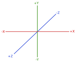
Right-handed System
OpenGL is a right-handed system:
